
 Tweet
Tweet
.. Kindly analyze this baseline report from APA and give us your "technical" evaluation... if you need more info on the specular analytics or Raleigh scattering results in the beam sector... don't hesitate 
Wooiiee mi rib kage!!
Chinese Absorbent Materials Technology
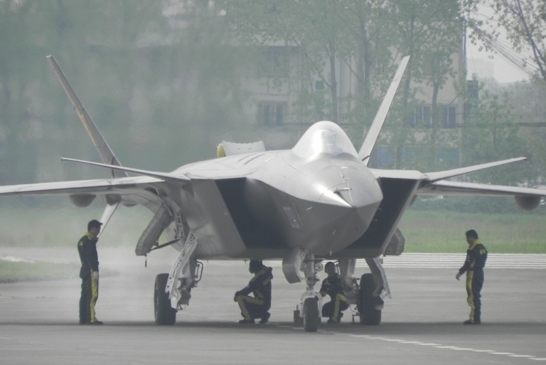 Rear quarter view of J-20 prototype showing the axi-symmetric nozzles and strakes
The state of Chinese research in low observables absorbent materials technology is not well understood in Western nations, as there have been no substantial official disclosures to date. The absence of disclosures, physical samples, or even viable imagery presents numerous challenges in determining what materials are intended for use in the J-20 design, or even what options are available to the Chengdu designers.
While official disclosures on production technologies are absent, these is a surprising number of recent unclassified basic research publications available, produced by Chinese researchers, dealing with the materials science of absorbers, especially Carbon Nano-Tube (CNT) absorbers, including absorbers loaded with conductive or magnetic materials. The number of papers and abstracts identified in this and related areas was of the order of thirty, mostly authored over the last several years, and published in English language journals and conferences. No attempt was made to survey Mandarin language publications.
Chinese research in RCS reduction is not confined to materials alone. A recent paper by Zhenghong and Mingliong details a derived Method of Moments algorithm for RCS computations6. Work by Jiang et al details the use of genetic algorithms for the optimal design of complex multilayer absorber structures7. Earlier research in conventional RCS modelling for design was produced by Cao et al8.
Most of the materials research papers and abstracts surveyed were experimental, involving the fabrication and subsequent performance parameter testing of the fabricated material. The deeper theoretical analysis of loss mechanisms, and theoretical study of material behaviour in production applications, are uncommon in openly published work from China. This in many respects emulates the pattern observed in many Soviet unclassified basic research publications during the Cold War period.
Annex B outlines the basic theoretical and practical concepts underpinning the design of absorbent materials.
Of specific interest in the context of Chinese stealth design is the respectable volume of high quality academic research performed on CNT, ferrite loaded epoxy, or other materials for use as the absorbent or lossy component in epoxy or other polymer matrix absorbent or lossy coatings, laminates, panels or radar absorbent structures9 - 30.
Radar Cross Section Simulation Method / Simulator Design and Capabilities
The Physical Optics (PO) method is used to predict the RCS of complex targets, in this instance the Chengdu J-20 prototype. The three dimensional model for any such target comprises a collection of triangular facets, with shared edges.
The scattered field from each and every visible facet, for a given angle pair {θ, Φ} in elevation and azimuth, is computed using the far field radiation integrals. It is assumed that the wavefront is planar and no parallax errors arise. The contributions from each of the facets are then summed to produce a total RCS for the angle pair {θ, Φ} in question. This method is a high frequency approximation that provides the best results for electrically large targets, and performs well in the specular direction.
The simulation uses geometric self-shadowing of facet calculations, such that RCS contributions hidden by shadowing airframe features are removed. This mechanism does not implement diffraction effects at larger wavelengths.
The PO RCS simulation program implementation has manageable run–times because it requires minimum computer resources. It is implemented in C++ language to provide shorter computation times than earlier Physical Optics simulators, such as the NPS POFacets code, which is implemented in the interpreted Matlab language5.
At this time the simulator does not implement surface travelling wave modelling and associated edge or gap backscatter modelling, or edge diffraction scattering effect modelling. As the backscatter from these, in real aircraft, depends upon leading and trailing edge absorbent treatments, it is a reasonable assumption that in a production design these RCS contributions would be strongly suppressed as a result of effective treatments, and thus the magnitude of these RCS contributions would be smaller than specular returns, from angles other than the peak mainlobes.
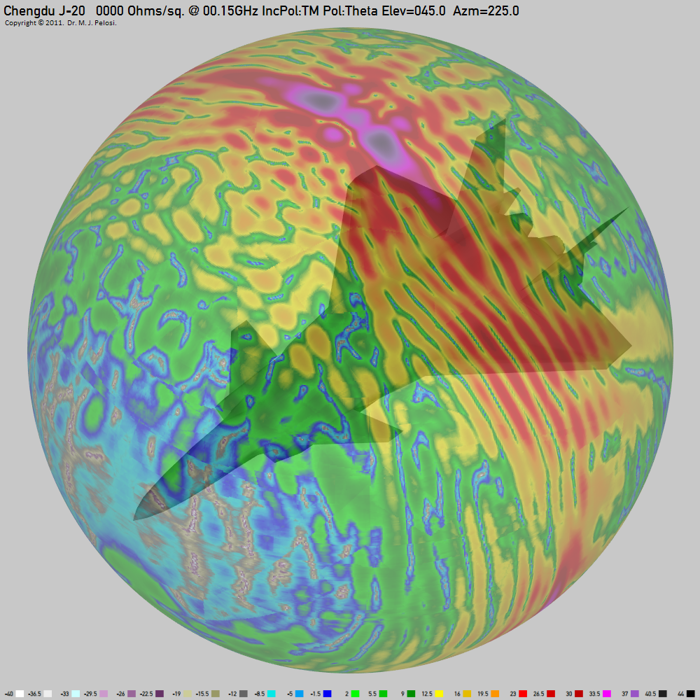
Example PolyChromatic Spherical Representation (PCSR) of J-20 specular RCS at 150 MHz. The dBSM value is represented by the colour scale at the bottom of the plot [Click to enlarge].
The second representation devised was labelled as the PolyChromatic Planar Representation (PCPR), in which a rectangular area is divided into tiles by aspect angle pair {θ, Φ}. The colour of each tile represents the RCS from the angular direction determined by the path between the tile and the centroid of the aircraft. The colour encoding of RCS employs the same ordered colour sequence as is employed in the PCSR scheme. All PCPR charts are further enhanced by the addition of rulers which separate the most critical azimuthal sectors, and elevation/depression angles.
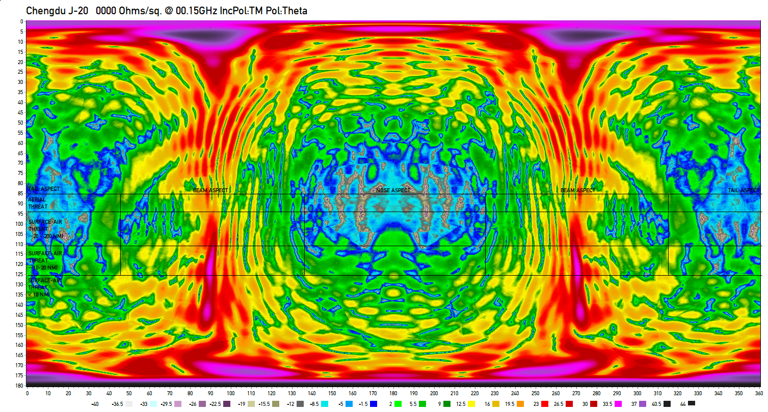
Example PolyChromatic Planar Representation (PCSR) of J-20 specular RCS at 150 MHz. The dBSM value is represented by the colour scale at the bottom of the plot. The rulers outline angular sectors of specific importance, from a survivability perspective [Click to enlarge].
The primary nose mounted radar antenna radome is assumed to be a bandpass design, emulating United States fighter designs, and was assumed to be fully opaque at all frequencies of interest. The model assumes an insignificant structural mode RCS contribution from the radar antenna face and radar bay bulkhead, consistent with a properly designed bandpass radome in its stopband region. Given the absence of any useful data on the internal configuration of the radome and antenna bay, a more elaborate model would be speculative, unavoidably. Imagery of the prototypes does not show any evidence of the radome join to the fuselage, possibly reflecting the absence of a radome on airframes built to validate aerodynamics, shaping and flight systems. In a production design the radome seam / join to the fuselage can produce significant RCS contributions if poorly implemented.
The engine inlet tunnels were modelled as Perfect Electrical Absorbers (PEA; Refer Annex E). Given the absence of any useful data on the internal configuration of the inlets and tunnels, a more elaborate model would again be entirely speculative. This is consistent with an ideal S-bend inlet tunnel clad with ideal RAM on its interior walls, and the use of an ideal engine face blocker. This is an optimistic assumption given historically observed difficulties in inlet tunnel signature reduction, as in many designs the inlet tunnel cavity RCS is a dominant wideband contributor in the forward aspect.
The exhaust tailpipe RCS contributions were also modelled as Perfect Electrical Absorbers (PEA). Given the absence of any useful data on the internal configuration of the tailpipes, a more elaborate model would be as before entirely speculative. The PEA model is consistent with an ideal tailpipe internally clad with ideal heat resistant RAM, and the use of an ideal turbine face and afterburner fuel spraybar blocker. This is an inherently optimistic assumption, as can be shown by employing an approximate model for an untreated tailpipe cavity, accounting for the reduction in projected nozzle area. This is detailed in Annex C.
The cockpit canopy transparency was modelled as a Perfect Electrical Conductor (PEC; Refer Annex E), to emulate the effect of a gold or other highly conductive plating layer in the polycarbonate laminate structure.
The closed axisymmetric exhaust nozzle employs a stacked serrated trailing edge in the manner of the F-35 nozzle, reflecting photographic imagery of the prototype. As the structural shape of the gaps between nozzle petals is not known at this time, we modelled the open nozzle as simple cylinder.
The photographic imagery of the J-20 prototypes was not of sufficient quality to incorporate any useful detail of panel join boundaries, door boundaries, and other surface features which produce RCS contributions due to surface travelling waves coupled to the aircraft skin. Even were such detail available, there is no guarantee production aircraft would retain the prototype configuration, reducing the value of any such results.
The position of the canards, delta wing leading and trailing edge surfaces, and fully moving tail surfaces was set to neutral, reflecting an optimal cruise configuration at nominal supercruise altitudes and airspeeds. Large deflections by these control surfaces in flight would produce large but transient increases in specular backscatter.
The geometrical fidelity of the model was assessed by comparison with high resolution imagery released in January, 2011, specifically by comparing the shape of the model from the same aspect as the photograph. Particular attention was paid to the fidelity of angles, especially in the chines, engine inlet exterior, planform and wing/fuselage joins, as these determine the {θ, Φ} directions of the mainlobes and sidelobes in the specular returns.
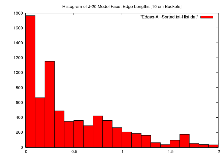
To establish the robustness of the 3D model for physical optics modelling, we explored the statistical distribution of edge lengths [x-axis] in the facet population [y-axis]. A substantial fraction of the facets are sufficiently large to yield good accuracy through most of the frequency bands being modelled for.
What the Simulation Does Not Demonstrate
The simulator at this time does not model backscatter from edge diffraction effects, although the resulting error will be mitigated by the reality that in a mature production design these RCS contributions are reduced by edge treatments;
The simulator at this time does not model backscatter from surface travelling wave effects. In the forward and aft hemispheres these can be dominant scattering sources where specular contributions are low. The magnitude of these RCS contributions is reduced by edge treatments, lossy surface coatings, gap treatments, and panel serrations;
The simulator at this time does not model backscatter from the AESA bay in the passband of a bandpass radome, due to the absence of any data on the intended design of same, the resulting error will be mitigated by the reality that in a mature production design much effort will be expended in suppressing passband RCS contributions;
The simulator at this time does not model backscatter from the engine inlet tunnels or engine exhaust tailpipes, due to the absence of any data on the intended design of same. In the forward and aft hemispheres these can be dominant scattering sources where specular contributions are low. The magnitude of these RCS contributions is reduced by suppressing these RCS contributions with absorbers, and in the case of inlet tunnels, by introducing a serpentine geometry to increase the number of bounces;
The simulator at this time does not model structural mode RCS contributions from antenna and EO apertures, panel joins, panel and door gaps, fasteners and other minor contributors; although the resulting error will be mitigated by the reality that in a mature production design these RCS contributions are reduced by RCS reduction treatments.
The PO computational algorithm performs most accurately at broadside or near normal angles of incidence, with decreasing accuracy at increasingly shallow angles of incidence, reflecting the limitions of PO modelling. The simulator does not implement the Mitzner/Ufimtsev corrections for edge currents. While a number of test runs with basic shapes showed good agreement between the PO simulation and backscatter peaks in third party test sample measurements, even at incidence angles below 10°, characteristically PO will underestimate backscatter in nulls. This limitation must be considered when assessing results for the nose and tail aspects, where most specular RCS contributions arise at very shallow angles39.
The PO computational algorithm performs best where the product of wave number and dimension ka ≥ 5, where k ≈ 2πf [Table 5.1 in (1)], yielding errors much less than 1 dB. Knott cites good agreement for cylinders as small as 1.5 wavelengths in diameter1.
The simulator does not account for a number of environmental factors, such as air density profile at the aircraft skin boundary layer, thermal variations in absorbent material properties, and moisture precipitation. RCS contributions from these sources are negligible for the principal lobe magnitudes studied.
In practical terms, the combination of the J-20 aircraft geometry and the use of the PO method without the Mitzner/Ufimtsev edge current corrections will yield errors at the frequencies of interest of less than 1 dB for the beam aspect and tail aspect sectors, which both have dominant specular scatterers. The nose aspect angular sector results will underestimate RCS, in part due to the absence of shallow angle specular contributions not modelled by the Mitzner/Ufimtsev edge current corrections, and by the absence of surface travelling wave backscatter contributions from surface features, gaps and trailing edges.
In all instances, the errors arising from the limitations of the PO computation method all fall into areas where well established RCS reduction treatments using RAS, RAM or coatings would be used, thus reducing the relative magnitude of the errors in the resulting RCS result for angles other than the peak mainlobes produced by these backscatter sources.
Importantly, even were the simulator capable of modelling shallow angle specular and non-specular RCS contributors, the PLA would not permit sufficiently detailed disclosures on the RCS reduction treatments applied to the airframe design, as a result of which reasonable assumed parameters would have to be applied instead of actual values.
The latter underscores the difficulty in attempting to perform highly accurate numerical RCS modelling of foreign airframe designs, where access to high fidelity shaping data, surface feature data, and materials type and application is actively denied.
What the Simulation Does Demonstrate
The simulation can accurately capture the direction of mainlobes and sidelobes produced by specular backscatter returns, especially where major specular reflectors produce strong contributions; this includes broadside and lesser specular returns from the wings, control surfaces and major reflecting areas of the fuselage, inlet exteriors and nozzles;
For an untreated PEC skin, the simulation can accurately capture the absolute and relative magnitudes of mainlobes and sidelobes produced by specular backscatter returns, especially where major specular reflectors produce strong contributions; this includes broadside and lesser specular returns from the wings, control surfaces and major reflecting areas of the fuselage, inlet exteriors and nozzles;
In capturing mainlobes and sidelobes of major specular scatterers it permits an assessment of the angular extent in the nose and tail sectors where diffraction and surface travelling wave backscatter is dominant, and can still be suppressed effectively;
Where a RAM surface treatment is applied in the model, it will present inferior RCS reduction performance to an actual treatment; so results produced will present a worst case performance result, to an order of magnitude.
In summary, if the results of the Physical Optics specular return modelling yield RCS values from key aspects, at key frequencies, which are consistent with stated VLO performance values in US designs, to an order of magnitude, it is reasonable to conclude that a mature J-20 design will qualify as a genuine VLO design.
Specular Radar Cross Section Simulation Results
Specular RCS was modelled for full spherical all-aspect coverage, for nine frequencies of interest. Frequencies were carefully chosen to match likely threat systems the J-20 would be intended to defeat in an operational environment. There are:
150 MHz to defeat Russian built VHF band Counter-VLO radars such as the Nebo UE, Nebo SVU and Nebo M series, or the Rezonans N/NE series;
600 MHz to defeat UHF band radars such as those carried by the E-2C/D AEW&C system, or the widely used Russian Kasta 2/2E and P-15/19 Flat Face / Squat Eye series;
1.2 GHz to defeat L-band surface based search, acquisition and GCI radars, and the Northrop-Grumman MESA AEW&C radar;
3.0 GHz to defeat widely used S-band acquisition radars, and the E-3 APY-1/APY-2 AWACS system;
6.0 GHz to defeat C-band Surface-Air-Missile engagement radars such as the MPQ-53/65 Patriot system;
8.0 GHz to defeat a range of X-band airborne fighter radars, Surface-Air-Missile engagement radars such as the 30N6E Flap Lid / Tomb Stone, and 92N6E Grave Stone, and a range of Western and Russian Surface-Air-Missile seekers;
12.0 GHz to defeat a range of X-band airborne fighter radars, Surface-Air-Missile engagement radars, and Surface-Air-Missile and Air-Air-Missile seekers;
16.0 GHz to defeat a range of Ku-band airborne fighter radars, and Surface-Air-Missile engagement radars, and Surface-Air-Missile and Air-Air-Missile seekers;
28.0 GHz to defeat a range of K-band missile seekers, and Surface-Air-Missile engagement radars;
RCS simulation results are presented in PCSR and PCPR formats. The latter includes rulers to show the most important elevation/depression angle rings/zones, and the four azimuthal quadrants.
Analysis of Shape Related Specular Radar Cross Section
The results of the physical optics simulation modelling of specular RCS for the J-20 shape, using an idealised PEC skin for all external surfaces, are displayed in Tables 1 and 2, for a vertically polarised E component. An additional simulation was performed at 150 MHz, or a horizontally polarised E component, with results in Tables 1A and 2A.
Results have been plotted in PCSR format for nine different aspects, and nine different frequencies. PCPR format plots have been produced for nine different frequencies.

Table 1. J-20 Specular RCS Model Results PEC [V-Pol]
Notation: The POFACETS simulator labels V-pol as “TM-z”, i.e. the magnetic H vector is transverse to the z-axis or vertical. This convention was retained for consistency in these simulation plots, with plots labelled TM being V-pol and plots labelled TE being H-pol5.
Table 2. J-20 Specular RCS Model Results PEC [V-Pol]
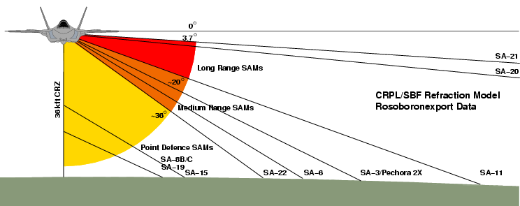
Threat depression angles as a function of type and missile kinematic range, for various contemporary and legacy SAM systems of Russian/Soviet manufacture (C. Kopp).
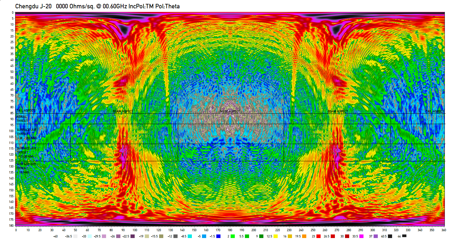
Table 1A. J-20 150 MHz Specular RCS Model Results PEC [H-Pol]
The starting point for any forensic analysis of the RCS of a new and hitherto unknown aircraft type is the study of the RCS of its shape, assuming a perfectly electrically conductive surface. This will permit identification of mainlobes and sidelobes, and their respective angular locations.
As the simulation technique is confined to the Physical Optics method, care must be taken in the interpretation of results, as at grazing or shallow angles of incidence the method will usually underestimate the magnitude of the RCS. In the most critical nose and tail aspect angular sectors, a good design will have no major scattering sources producing specular returns captured by the simulation, and the RCS will be dominated by nonspecular mechanisms, primarily diffraction and surface travelling waves, engine inlet and exhaust backscatter, as well as the structural mode RCS of antennas, panel join gaps, or other electrical apertures35.
Table 2 Legend:
NOSE ASPECT Azimuthal Sector 90° centred on aircraft nose
TAIL ASPECT Azimuthal Sector 90° centred on aircraft tail
BEAM ASPECT Azimuthal Sector 90° centred on aircraft side
AERIAL THREAT
Depression Angle Ring -5° - 3.7° aircraft at similar altitudes
SURFACE-AIR THREAT ~20 - 200 NMI
Depression Angle Ring ~3.7° - 20° SAM at 200 down to 20 NMI
SURFACE-AIR THREAT ~10 - 20 NMI Depression Angle Ring ~20° - 36° SAM at 20 down to 10 NMI
SURFACE-AIR THREAT <10 NMI Depression Angle Ring
~36° SAM inside 10 NMI
Assumptions:
A.Distant threats CRPL exponential refractive atmospheric model;
B.Near threats SBF refractive atmospheric model;
C.Spherical earth model;
D.Assumed aircraft altitude 36 kft;
E.For higher aircraft altitudes the depression angles increase for nearer threats.
Behaviour in the nose aspect angular sector, defined as ±45° in azimuth left and right of the nose, and between +5° in elevation, and -36° in depression, is generally very good across all bands simulated. No scattering sources producing significant specular RCS are observed at 3 GHz or any higher frequencies. The RCS performance will thus satisfy the Very Low Observable requirement that strong specular returns are absent. In this angular and frequency domain, the actual RCS performance of the design will be dominated by edge alignment to control diffracting edge mainlobe directions, and applied RAM and RAS. As the simulation cannot capture the behaviour of the inlet edges and tunnels, these peaks are absent.
At L-band and below, there is a pronounced increase in the calculated RCS within the nose aspect angular sector. This is a byproduct of the breakdown of the directional effect produced by smaller shaping features, which lose their ability to concentrate backscatter into narrow mainlobes. Indeed many physically smaller specular and diffractive regime optimised shaping features fall into the Raleigh scattering regime and lose effect wholly.
Behaviour in the tail aspect angular sector, defined as ±45° in azimuth left and right of the tail, and between +5° in elevation, and -36° in depression, is dominated by the scattering behaviour of the pair of axisymmetric nozzles, which has major specular, cavity and diffractive contributors, detailed in Annex C. The large diffraction backscatter from the nozzle rims below X-band is not captured in the Physical Optics simulation, the tailpipe cavity backscatter is not represented, and the distinctive lobing structure of the nozzle petals above X-band is also not visible.
There are two prominent mainlobes at ~±15° in azimuth left and right of the tail, centred at a depression angle of ~20° to ~40°, produced by the vertical tails which are not shadowed by a horizontal stabilator as would be employed in a conventional airframe design. While these produce strong specular returns, the depression angle through the centre of these mainlobes varies strongly with changing azimuth angle, and thus would present at any fixed depression angle only a narrow transient flash for a single azimuth.
Behaviour in the left and right beam aspect angular sectors, defined as ±45° in azimuth left and right of the beam, and between +5° in elevation, and -36° in depression, is dominated by the scattering behaviour of the almost flat slab sides, canted vertical tail surfaces, strakes, and specular return from the nozzles. This could be described as classical “bowtie” lobing behaviour.
The specular return from the nozzles produces a pronounced mainlobe at 20° to 25° aft of the airframe beam, through most of the elevation band, with most of the mainlobe contained within a 10° degree width. There is a strong interference pattern discernable in the mainlobe, as the backscatter from the paired nozzles constructively and destructively interferes with changing aspect angle.
The primary mainlobe produced by the slab fuselage sides is unusually wide in the azimuthal dimension at ~20° below the S-band as a result of the complex side curvature introduced by area ruling, for aerodynamic reasons. In the Ku-band the mainlobe separates into multiple closely spaced peaks, each associated with a particular extent of the fuselage side.
The extent to which the specular mainlobes in a ventral slab sided design, these including the J-20, T-50 PAK-FA, F-35 and F-22, should be made as narrow as possible, depends primarily on whether the aircraft is intended to penetrate an IADS deeply or not. The wider these lobes are, the greater the exposure time of the aircraft to a distant beam aspect threat, such as a missile battery.
The overall conclusions which can be drawn from a forensic analysis of the shape of the J-20 prototype across the bands of interest are as follows:
The nose aspect sector has excellent potential for achieving Very Low Observable performance due to the absence of any major specular scatterers;
The tail aspect sector is largely degraded in RCS performance by the use of axi-symmetric nozzles which introduce strong specular and diffraction returns; the nozzles destroy the otherwise very reasonable behaviour of the rest of the airframe in this angular sector; the tail surface geometry introduces a further degradation in performance, but constrained to narrow lobes;
The beam aspect sector shows classical “bowtie” lobing behaviour, but the lobe widths are wider than otherwise necessary due to the use of smooth area ruling rather than discrete geometrically flat area segments.
If the production J-20 retains the axisymmetric nozzles and smoothly area ruled sides, the aircraft could at best deliver robust Very Low Observable performance in the nose aspect angular sector.
If the production J-20 introduces a rectangular faceted nozzle design, and refinements to fuselage side shaping, the design would present very good potential for robust Very Low Observable performance in the S-band and above, in the nose and tail aspect angular sectors, and viable Low Observable performance above the S-band in the beam aspect angular sector.
Analysis of Specular RCS with a Representative RAM Coating
The results of the physical optics simulation modelling of specular RCS for the J-20 shape, using a RAM coating model for all external surfaces, are displayed in Tables 3 and 4. The RAM coating parameters are discussed below.
Modelling a RAM coated J-20 presents a number of interesting challenges, especially since so little is known about the materials available to Chengdu engineers, and the construction technique used on the airframe. It is not yet known with any confidence whether the J-20 is covered with metal alloy skin panels, carbon fibre composite skin panels, or some combination of the two. Moreover, if we consider the Russian Flanker as a case study, metal skin panels were progressively replaced with composite panels in later variants, so it is entirely conceivable that a metal skinned J-20 prototype could evolve over time into a composite skinned production vehicle.

Aircraft built for VLO will employ a range of specialised materials, applied to specific portions of the airframe to achieve very specific loss characteristics at specific frequencies. Unique materials would be employed to control specular returns, surface travelling wave returns, and edge returns, all from specific key aspects.
A Physical Optics simulator can model specular returns, but the simulator employed for this study does not at this time incorporate surface travelling wave effects, and edge diffraction effects. Therefore a materials model which addressed the latter two scattering mechanisms would only impact a specular RCS model through the behaviour of these otherwise optimised materials in a specular scattering regime at larger angles of incidence.
At this time there are two well known strategies for the application of absorbers to aircraft.
The first strategy is to construct the aircraft with skin panels comprising different, structurally optimised materials, then coat the whole airframe with a highly conductive coating, such as a silver suspension in epoxy, and then robotically apply one or more coats of an epoxy or urethane matrix based RAM material. Weight will constraint coating thickness, for large areas, to as little as ~1 mm.
It is important to note that if an absorber presents a strong impedance mismatch to free space, the reflection from the mismatch will set an asymptotic bound on achievable RCS reduction of specular returns. Increasing material loss performance or thickness will not improve performance beyond this asymptotic bound.
No attempt was made to model treatments for surface travelling wave backscatter, as insufficient data was available on the geometry of panel and control surface boundaries, and as noted earlier, the choice of skin materials is unknown. The intent behind such treatments is to minimise the impedance mismatch at a panel boundary, or trailing edge, seen by a surface travelling wave attached to the skin of the aircraft40.
Where disimilar skin materials are employed without substantial absorbent coatings, for instance, matching the impedance at the boundary between two panels of strongly differing impedance, would require a low impedance coating on the higher impedance panel, which would be far from the optimum required for broadside specular backscatter reduction. Treatment of trailing edges typically requires materials with high permeability, also suboptimal for specular backscatter reduction40.
Stability of surface materials with changing temperature is a major consideration, given the wide operating temperature range experienced by supersonic gas turbine powered military aircraft. Stability with surface materials age is also important, especially for the second implementation strategy where an age related degradation in material performance incurs a very high cost in skin panel replacement. Neither of these considerations were addressed in this study.
The final choice in modelling the J-20 was to employ the second implementation strategy where the aircraft is assumed to be constructed with composite skin panels either loaded with RAM, or laminated in production with a RAM sheet. The “matched wave impedance” approach was assumed, although none of the published Chinese materials possessed the required properties.
This choice of using the second strategy was made as the intent of this study was to explore the long term potential for good Very Low Observable performance in the J-20 design. Composite skins with embedded absorbers provide greater RAM depth and thus better performance with a less mature RAM technology base. They are also less demanding in terms of handling in an operational environment, a major advantage for an operator reliant on less experienced conscript maintenance personnel.
A question of interest which arose during this effort was that of which frequency bands the designers of the J-20 might optimise the design of a specular RAM coating for. Prima facie this may appear to be a simple question, but it is not.
If we assume that combat attrition is a serious consideration in PLA-AF planning and design definition, then the two most obvious choices in optimisation are thus:
L-band through S-band - most suited for a design intended to penetrate deep into an opposing IADS, the intent of the RAM being to defeat early warning and acquisition radars;
X-band through Ku-band - most suited for a design intended to fight inside its own supporting IADS, the intent of the RAM being to defeat X-band fighter radars, and Ku-band missile seekers.
Unfortunately, PLA-AF reasoning in this area is not well understood in the West, given the limited disclosures made to date. In turn, application of Western design priorities may not yield an accurate estimation of the PLA-AF's relative priorities in the design.
A complicating factor is uncertainty surrounding the choice of axi-symmetric exhaust nozzle geometry and ventral strakes in the long term. It is entirely conceivable that a mature production J-20 might employ a faceted rectangular nozzle in the manner of the F-22, and be completed without the strakes. Were the latter to prove true, the more likely RAM optimisation would be L-band through S-band, conversely, if the axi-symmetric exhaust nozzle is retained to production, then an X-band through Ku-band optimisation would be more likely.
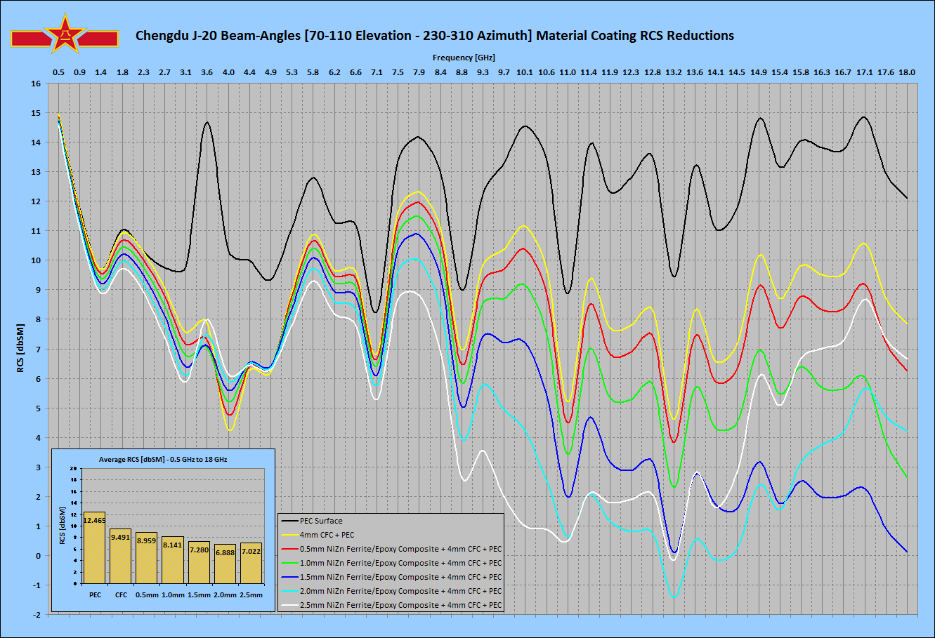
The final material combination employed was essentially “generic”, with an outer 2 mm epoxy layer loaded with a soft Ni-Zn ferrite (Configuration C, below), laminated with a 4 mm carbon fibre epoxy composite skin32.
Due to limited frequency coverage in data characterising the modelled RAM coating, simulations were performed only for six frequencies, from the L-band through to the Ku-band.
Some measure of the performance improvement achieved can be determined from the preceding chart, which shows specular RCS averaged across an angular extent in the beam aspect, across a range of frequencies. The beam aspect was chosen due to the dominant specular scatterers in this angular region. For a 2 mm ferrite loaded epoxy layer thickness laminated into a CFC panel, the absorber produces observable effect between S-band and Ku-band, improving with frequency. Best effect was achieved in the region of 12 GHz, of the order of 10 dB compared to PEC, all averaged across the same angular extent.
The variations in RCS behaviour observed with changing aspect reflect closely the behaviour observed with the PEC model simulation, detailed above. In particular, the RAM reduces the peak magnitude of and narrows the mainlobes in the specular return. This effect is most pronounced in the upper X-band and Ku-band, and weakest in the L-band.
In assessing what materials strategy to apply, several experimental simulations were performed to observe actual effectiveness, and the extent to which impedance mismatch impacted achievable RCS reduction.
The well characterised CNT/epoxy matrix RAM, by Zhang et al., was applied to a model of Zhang's test article used for measurement, and then as a 1 mm RAM coating over a PEC airframe skin, to establish whether this high permittivity material would be viable. The results reflected the strong impedance mismatch observed with the simulation of the initial test article, and this model was not pursued further. The material parameters are detailed in Table 5.
The more refined ferrite loaded Fe-filled CNT/epoxy matrix RAM by Gui et al., was not well characterised, so the published performance curves were employed to reverse engineer the complex permeability and permittivity values, using an RCS simulation of the test article employed by Gui et al., and an iterated guessing algorithm. This material also provided very poor impedance matching, reflected in a reduced resolution simulation of the airframe with a 1 mm coating over PEC. It was also not pursued further.
While the basic theoretical constraints for an impedance matched thin specular RAM coating predicted that neither material would be viable, it was nevertheless of interest to perform a quantitative simulation experiment to confirm this empirically.
A number of epoxy matrix coatings, using older and more recent ferrites, were also simulated, using a 4 mm thick carbon fibre epoxy composite substrate, emulating an aircraft skin.
The best specular RCS improvement observed involved the use of a theoretical impedance matched material, with real permeability and permittivity of ~15, and high loss tangents.
Table 3. J-20 Specular RCS Model Results With RAM / CFC [V-Pol]
[Click Thumbnail to Enlarge]
Wooiiee mi rib kage!!
Chinese Absorbent Materials Technology
Rear quarter view of J-20 prototype showing the axi-symmetric nozzles and strakesThe state of Chinese research in low observables absorbent materials technology is not well understood in Western nations, as there have been no substantial official disclosures to date. The absence of disclosures, physical samples, or even viable imagery presents numerous challenges in determining what materials are intended for use in the J-20 design, or even what options are available to the Chengdu designers.
While official disclosures on production technologies are absent, these is a surprising number of recent unclassified basic research publications available, produced by Chinese researchers, dealing with the materials science of absorbers, especially Carbon Nano-Tube (CNT) absorbers, including absorbers loaded with conductive or magnetic materials. The number of papers and abstracts identified in this and related areas was of the order of thirty, mostly authored over the last several years, and published in English language journals and conferences. No attempt was made to survey Mandarin language publications.
Chinese research in RCS reduction is not confined to materials alone. A recent paper by Zhenghong and Mingliong details a derived Method of Moments algorithm for RCS computations6. Work by Jiang et al details the use of genetic algorithms for the optimal design of complex multilayer absorber structures7. Earlier research in conventional RCS modelling for design was produced by Cao et al8.
Most of the materials research papers and abstracts surveyed were experimental, involving the fabrication and subsequent performance parameter testing of the fabricated material. The deeper theoretical analysis of loss mechanisms, and theoretical study of material behaviour in production applications, are uncommon in openly published work from China. This in many respects emulates the pattern observed in many Soviet unclassified basic research publications during the Cold War period.
Annex B outlines the basic theoretical and practical concepts underpinning the design of absorbent materials.
Of specific interest in the context of Chinese stealth design is the respectable volume of high quality academic research performed on CNT, ferrite loaded epoxy, or other materials for use as the absorbent or lossy component in epoxy or other polymer matrix absorbent or lossy coatings, laminates, panels or radar absorbent structures9 - 30.
Radar Cross Section Simulation Method / Simulator Design and Capabilities
The Physical Optics (PO) method is used to predict the RCS of complex targets, in this instance the Chengdu J-20 prototype. The three dimensional model for any such target comprises a collection of triangular facets, with shared edges.
The scattered field from each and every visible facet, for a given angle pair {θ, Φ} in elevation and azimuth, is computed using the far field radiation integrals. It is assumed that the wavefront is planar and no parallax errors arise. The contributions from each of the facets are then summed to produce a total RCS for the angle pair {θ, Φ} in question. This method is a high frequency approximation that provides the best results for electrically large targets, and performs well in the specular direction.
The simulation uses geometric self-shadowing of facet calculations, such that RCS contributions hidden by shadowing airframe features are removed. This mechanism does not implement diffraction effects at larger wavelengths.
The PO RCS simulation program implementation has manageable run–times because it requires minimum computer resources. It is implemented in C++ language to provide shorter computation times than earlier Physical Optics simulators, such as the NPS POFacets code, which is implemented in the interpreted Matlab language5.
At this time the simulator does not implement surface travelling wave modelling and associated edge or gap backscatter modelling, or edge diffraction scattering effect modelling. As the backscatter from these, in real aircraft, depends upon leading and trailing edge absorbent treatments, it is a reasonable assumption that in a production design these RCS contributions would be strongly suppressed as a result of effective treatments, and thus the magnitude of these RCS contributions would be smaller than specular returns, from angles other than the peak mainlobes.
Example PolyChromatic Spherical Representation (PCSR) of J-20 specular RCS at 150 MHz. The dBSM value is represented by the colour scale at the bottom of the plot [Click to enlarge].
The second representation devised was labelled as the PolyChromatic Planar Representation (PCPR), in which a rectangular area is divided into tiles by aspect angle pair {θ, Φ}. The colour of each tile represents the RCS from the angular direction determined by the path between the tile and the centroid of the aircraft. The colour encoding of RCS employs the same ordered colour sequence as is employed in the PCSR scheme. All PCPR charts are further enhanced by the addition of rulers which separate the most critical azimuthal sectors, and elevation/depression angles.
Example PolyChromatic Planar Representation (PCSR) of J-20 specular RCS at 150 MHz. The dBSM value is represented by the colour scale at the bottom of the plot. The rulers outline angular sectors of specific importance, from a survivability perspective [Click to enlarge].
The primary nose mounted radar antenna radome is assumed to be a bandpass design, emulating United States fighter designs, and was assumed to be fully opaque at all frequencies of interest. The model assumes an insignificant structural mode RCS contribution from the radar antenna face and radar bay bulkhead, consistent with a properly designed bandpass radome in its stopband region. Given the absence of any useful data on the internal configuration of the radome and antenna bay, a more elaborate model would be speculative, unavoidably. Imagery of the prototypes does not show any evidence of the radome join to the fuselage, possibly reflecting the absence of a radome on airframes built to validate aerodynamics, shaping and flight systems. In a production design the radome seam / join to the fuselage can produce significant RCS contributions if poorly implemented.
The engine inlet tunnels were modelled as Perfect Electrical Absorbers (PEA; Refer Annex E). Given the absence of any useful data on the internal configuration of the inlets and tunnels, a more elaborate model would again be entirely speculative. This is consistent with an ideal S-bend inlet tunnel clad with ideal RAM on its interior walls, and the use of an ideal engine face blocker. This is an optimistic assumption given historically observed difficulties in inlet tunnel signature reduction, as in many designs the inlet tunnel cavity RCS is a dominant wideband contributor in the forward aspect.
The exhaust tailpipe RCS contributions were also modelled as Perfect Electrical Absorbers (PEA). Given the absence of any useful data on the internal configuration of the tailpipes, a more elaborate model would be as before entirely speculative. The PEA model is consistent with an ideal tailpipe internally clad with ideal heat resistant RAM, and the use of an ideal turbine face and afterburner fuel spraybar blocker. This is an inherently optimistic assumption, as can be shown by employing an approximate model for an untreated tailpipe cavity, accounting for the reduction in projected nozzle area. This is detailed in Annex C.
The cockpit canopy transparency was modelled as a Perfect Electrical Conductor (PEC; Refer Annex E), to emulate the effect of a gold or other highly conductive plating layer in the polycarbonate laminate structure.
The closed axisymmetric exhaust nozzle employs a stacked serrated trailing edge in the manner of the F-35 nozzle, reflecting photographic imagery of the prototype. As the structural shape of the gaps between nozzle petals is not known at this time, we modelled the open nozzle as simple cylinder.
The photographic imagery of the J-20 prototypes was not of sufficient quality to incorporate any useful detail of panel join boundaries, door boundaries, and other surface features which produce RCS contributions due to surface travelling waves coupled to the aircraft skin. Even were such detail available, there is no guarantee production aircraft would retain the prototype configuration, reducing the value of any such results.
The position of the canards, delta wing leading and trailing edge surfaces, and fully moving tail surfaces was set to neutral, reflecting an optimal cruise configuration at nominal supercruise altitudes and airspeeds. Large deflections by these control surfaces in flight would produce large but transient increases in specular backscatter.
The geometrical fidelity of the model was assessed by comparison with high resolution imagery released in January, 2011, specifically by comparing the shape of the model from the same aspect as the photograph. Particular attention was paid to the fidelity of angles, especially in the chines, engine inlet exterior, planform and wing/fuselage joins, as these determine the {θ, Φ} directions of the mainlobes and sidelobes in the specular returns.
To establish the robustness of the 3D model for physical optics modelling, we explored the statistical distribution of edge lengths [x-axis] in the facet population [y-axis]. A substantial fraction of the facets are sufficiently large to yield good accuracy through most of the frequency bands being modelled for.
What the Simulation Does Not Demonstrate
The simulator at this time does not model backscatter from edge diffraction effects, although the resulting error will be mitigated by the reality that in a mature production design these RCS contributions are reduced by edge treatments;
The simulator at this time does not model backscatter from surface travelling wave effects. In the forward and aft hemispheres these can be dominant scattering sources where specular contributions are low. The magnitude of these RCS contributions is reduced by edge treatments, lossy surface coatings, gap treatments, and panel serrations;
The simulator at this time does not model backscatter from the AESA bay in the passband of a bandpass radome, due to the absence of any data on the intended design of same, the resulting error will be mitigated by the reality that in a mature production design much effort will be expended in suppressing passband RCS contributions;
The simulator at this time does not model backscatter from the engine inlet tunnels or engine exhaust tailpipes, due to the absence of any data on the intended design of same. In the forward and aft hemispheres these can be dominant scattering sources where specular contributions are low. The magnitude of these RCS contributions is reduced by suppressing these RCS contributions with absorbers, and in the case of inlet tunnels, by introducing a serpentine geometry to increase the number of bounces;
The simulator at this time does not model structural mode RCS contributions from antenna and EO apertures, panel joins, panel and door gaps, fasteners and other minor contributors; although the resulting error will be mitigated by the reality that in a mature production design these RCS contributions are reduced by RCS reduction treatments.
The PO computational algorithm performs most accurately at broadside or near normal angles of incidence, with decreasing accuracy at increasingly shallow angles of incidence, reflecting the limitions of PO modelling. The simulator does not implement the Mitzner/Ufimtsev corrections for edge currents. While a number of test runs with basic shapes showed good agreement between the PO simulation and backscatter peaks in third party test sample measurements, even at incidence angles below 10°, characteristically PO will underestimate backscatter in nulls. This limitation must be considered when assessing results for the nose and tail aspects, where most specular RCS contributions arise at very shallow angles39.
The PO computational algorithm performs best where the product of wave number and dimension ka ≥ 5, where k ≈ 2πf [Table 5.1 in (1)], yielding errors much less than 1 dB. Knott cites good agreement for cylinders as small as 1.5 wavelengths in diameter1.
The simulator does not account for a number of environmental factors, such as air density profile at the aircraft skin boundary layer, thermal variations in absorbent material properties, and moisture precipitation. RCS contributions from these sources are negligible for the principal lobe magnitudes studied.
In practical terms, the combination of the J-20 aircraft geometry and the use of the PO method without the Mitzner/Ufimtsev edge current corrections will yield errors at the frequencies of interest of less than 1 dB for the beam aspect and tail aspect sectors, which both have dominant specular scatterers. The nose aspect angular sector results will underestimate RCS, in part due to the absence of shallow angle specular contributions not modelled by the Mitzner/Ufimtsev edge current corrections, and by the absence of surface travelling wave backscatter contributions from surface features, gaps and trailing edges.
In all instances, the errors arising from the limitations of the PO computation method all fall into areas where well established RCS reduction treatments using RAS, RAM or coatings would be used, thus reducing the relative magnitude of the errors in the resulting RCS result for angles other than the peak mainlobes produced by these backscatter sources.
Importantly, even were the simulator capable of modelling shallow angle specular and non-specular RCS contributors, the PLA would not permit sufficiently detailed disclosures on the RCS reduction treatments applied to the airframe design, as a result of which reasonable assumed parameters would have to be applied instead of actual values.
The latter underscores the difficulty in attempting to perform highly accurate numerical RCS modelling of foreign airframe designs, where access to high fidelity shaping data, surface feature data, and materials type and application is actively denied.
What the Simulation Does Demonstrate
The simulation can accurately capture the direction of mainlobes and sidelobes produced by specular backscatter returns, especially where major specular reflectors produce strong contributions; this includes broadside and lesser specular returns from the wings, control surfaces and major reflecting areas of the fuselage, inlet exteriors and nozzles;
For an untreated PEC skin, the simulation can accurately capture the absolute and relative magnitudes of mainlobes and sidelobes produced by specular backscatter returns, especially where major specular reflectors produce strong contributions; this includes broadside and lesser specular returns from the wings, control surfaces and major reflecting areas of the fuselage, inlet exteriors and nozzles;
In capturing mainlobes and sidelobes of major specular scatterers it permits an assessment of the angular extent in the nose and tail sectors where diffraction and surface travelling wave backscatter is dominant, and can still be suppressed effectively;
Where a RAM surface treatment is applied in the model, it will present inferior RCS reduction performance to an actual treatment; so results produced will present a worst case performance result, to an order of magnitude.
In summary, if the results of the Physical Optics specular return modelling yield RCS values from key aspects, at key frequencies, which are consistent with stated VLO performance values in US designs, to an order of magnitude, it is reasonable to conclude that a mature J-20 design will qualify as a genuine VLO design.
Specular Radar Cross Section Simulation Results
Specular RCS was modelled for full spherical all-aspect coverage, for nine frequencies of interest. Frequencies were carefully chosen to match likely threat systems the J-20 would be intended to defeat in an operational environment. There are:
150 MHz to defeat Russian built VHF band Counter-VLO radars such as the Nebo UE, Nebo SVU and Nebo M series, or the Rezonans N/NE series;
600 MHz to defeat UHF band radars such as those carried by the E-2C/D AEW&C system, or the widely used Russian Kasta 2/2E and P-15/19 Flat Face / Squat Eye series;
1.2 GHz to defeat L-band surface based search, acquisition and GCI radars, and the Northrop-Grumman MESA AEW&C radar;
3.0 GHz to defeat widely used S-band acquisition radars, and the E-3 APY-1/APY-2 AWACS system;
6.0 GHz to defeat C-band Surface-Air-Missile engagement radars such as the MPQ-53/65 Patriot system;
8.0 GHz to defeat a range of X-band airborne fighter radars, Surface-Air-Missile engagement radars such as the 30N6E Flap Lid / Tomb Stone, and 92N6E Grave Stone, and a range of Western and Russian Surface-Air-Missile seekers;
12.0 GHz to defeat a range of X-band airborne fighter radars, Surface-Air-Missile engagement radars, and Surface-Air-Missile and Air-Air-Missile seekers;
16.0 GHz to defeat a range of Ku-band airborne fighter radars, and Surface-Air-Missile engagement radars, and Surface-Air-Missile and Air-Air-Missile seekers;
28.0 GHz to defeat a range of K-band missile seekers, and Surface-Air-Missile engagement radars;
RCS simulation results are presented in PCSR and PCPR formats. The latter includes rulers to show the most important elevation/depression angle rings/zones, and the four azimuthal quadrants.
Analysis of Shape Related Specular Radar Cross Section
The results of the physical optics simulation modelling of specular RCS for the J-20 shape, using an idealised PEC skin for all external surfaces, are displayed in Tables 1 and 2, for a vertically polarised E component. An additional simulation was performed at 150 MHz, or a horizontally polarised E component, with results in Tables 1A and 2A.
Results have been plotted in PCSR format for nine different aspects, and nine different frequencies. PCPR format plots have been produced for nine different frequencies.
Table 1. J-20 Specular RCS Model Results PEC [V-Pol]
Notation: The POFACETS simulator labels V-pol as “TM-z”, i.e. the magnetic H vector is transverse to the z-axis or vertical. This convention was retained for consistency in these simulation plots, with plots labelled TM being V-pol and plots labelled TE being H-pol5.
Table 2. J-20 Specular RCS Model Results PEC [V-Pol]
Threat depression angles as a function of type and missile kinematic range, for various contemporary and legacy SAM systems of Russian/Soviet manufacture (C. Kopp).
Table 1A. J-20 150 MHz Specular RCS Model Results PEC [H-Pol]
The starting point for any forensic analysis of the RCS of a new and hitherto unknown aircraft type is the study of the RCS of its shape, assuming a perfectly electrically conductive surface. This will permit identification of mainlobes and sidelobes, and their respective angular locations.
As the simulation technique is confined to the Physical Optics method, care must be taken in the interpretation of results, as at grazing or shallow angles of incidence the method will usually underestimate the magnitude of the RCS. In the most critical nose and tail aspect angular sectors, a good design will have no major scattering sources producing specular returns captured by the simulation, and the RCS will be dominated by nonspecular mechanisms, primarily diffraction and surface travelling waves, engine inlet and exhaust backscatter, as well as the structural mode RCS of antennas, panel join gaps, or other electrical apertures35.
Table 2 Legend:
NOSE ASPECT Azimuthal Sector 90° centred on aircraft nose
TAIL ASPECT Azimuthal Sector 90° centred on aircraft tail
BEAM ASPECT Azimuthal Sector 90° centred on aircraft side
AERIAL THREAT
Depression Angle Ring -5° - 3.7° aircraft at similar altitudes
SURFACE-AIR THREAT ~20 - 200 NMI
Depression Angle Ring ~3.7° - 20° SAM at 200 down to 20 NMI
SURFACE-AIR THREAT ~10 - 20 NMI Depression Angle Ring ~20° - 36° SAM at 20 down to 10 NMI
SURFACE-AIR THREAT <10 NMI Depression Angle Ring
~36° SAM inside 10 NMI
Assumptions:
A.Distant threats CRPL exponential refractive atmospheric model;
B.Near threats SBF refractive atmospheric model;
C.Spherical earth model;
D.Assumed aircraft altitude 36 kft;
E.For higher aircraft altitudes the depression angles increase for nearer threats.
Behaviour in the nose aspect angular sector, defined as ±45° in azimuth left and right of the nose, and between +5° in elevation, and -36° in depression, is generally very good across all bands simulated. No scattering sources producing significant specular RCS are observed at 3 GHz or any higher frequencies. The RCS performance will thus satisfy the Very Low Observable requirement that strong specular returns are absent. In this angular and frequency domain, the actual RCS performance of the design will be dominated by edge alignment to control diffracting edge mainlobe directions, and applied RAM and RAS. As the simulation cannot capture the behaviour of the inlet edges and tunnels, these peaks are absent.
At L-band and below, there is a pronounced increase in the calculated RCS within the nose aspect angular sector. This is a byproduct of the breakdown of the directional effect produced by smaller shaping features, which lose their ability to concentrate backscatter into narrow mainlobes. Indeed many physically smaller specular and diffractive regime optimised shaping features fall into the Raleigh scattering regime and lose effect wholly.
Behaviour in the tail aspect angular sector, defined as ±45° in azimuth left and right of the tail, and between +5° in elevation, and -36° in depression, is dominated by the scattering behaviour of the pair of axisymmetric nozzles, which has major specular, cavity and diffractive contributors, detailed in Annex C. The large diffraction backscatter from the nozzle rims below X-band is not captured in the Physical Optics simulation, the tailpipe cavity backscatter is not represented, and the distinctive lobing structure of the nozzle petals above X-band is also not visible.
There are two prominent mainlobes at ~±15° in azimuth left and right of the tail, centred at a depression angle of ~20° to ~40°, produced by the vertical tails which are not shadowed by a horizontal stabilator as would be employed in a conventional airframe design. While these produce strong specular returns, the depression angle through the centre of these mainlobes varies strongly with changing azimuth angle, and thus would present at any fixed depression angle only a narrow transient flash for a single azimuth.
Behaviour in the left and right beam aspect angular sectors, defined as ±45° in azimuth left and right of the beam, and between +5° in elevation, and -36° in depression, is dominated by the scattering behaviour of the almost flat slab sides, canted vertical tail surfaces, strakes, and specular return from the nozzles. This could be described as classical “bowtie” lobing behaviour.
The specular return from the nozzles produces a pronounced mainlobe at 20° to 25° aft of the airframe beam, through most of the elevation band, with most of the mainlobe contained within a 10° degree width. There is a strong interference pattern discernable in the mainlobe, as the backscatter from the paired nozzles constructively and destructively interferes with changing aspect angle.
The primary mainlobe produced by the slab fuselage sides is unusually wide in the azimuthal dimension at ~20° below the S-band as a result of the complex side curvature introduced by area ruling, for aerodynamic reasons. In the Ku-band the mainlobe separates into multiple closely spaced peaks, each associated with a particular extent of the fuselage side.
The extent to which the specular mainlobes in a ventral slab sided design, these including the J-20, T-50 PAK-FA, F-35 and F-22, should be made as narrow as possible, depends primarily on whether the aircraft is intended to penetrate an IADS deeply or not. The wider these lobes are, the greater the exposure time of the aircraft to a distant beam aspect threat, such as a missile battery.
The overall conclusions which can be drawn from a forensic analysis of the shape of the J-20 prototype across the bands of interest are as follows:
The nose aspect sector has excellent potential for achieving Very Low Observable performance due to the absence of any major specular scatterers;
The tail aspect sector is largely degraded in RCS performance by the use of axi-symmetric nozzles which introduce strong specular and diffraction returns; the nozzles destroy the otherwise very reasonable behaviour of the rest of the airframe in this angular sector; the tail surface geometry introduces a further degradation in performance, but constrained to narrow lobes;
The beam aspect sector shows classical “bowtie” lobing behaviour, but the lobe widths are wider than otherwise necessary due to the use of smooth area ruling rather than discrete geometrically flat area segments.
If the production J-20 retains the axisymmetric nozzles and smoothly area ruled sides, the aircraft could at best deliver robust Very Low Observable performance in the nose aspect angular sector.
If the production J-20 introduces a rectangular faceted nozzle design, and refinements to fuselage side shaping, the design would present very good potential for robust Very Low Observable performance in the S-band and above, in the nose and tail aspect angular sectors, and viable Low Observable performance above the S-band in the beam aspect angular sector.
Analysis of Specular RCS with a Representative RAM Coating
The results of the physical optics simulation modelling of specular RCS for the J-20 shape, using a RAM coating model for all external surfaces, are displayed in Tables 3 and 4. The RAM coating parameters are discussed below.
Modelling a RAM coated J-20 presents a number of interesting challenges, especially since so little is known about the materials available to Chengdu engineers, and the construction technique used on the airframe. It is not yet known with any confidence whether the J-20 is covered with metal alloy skin panels, carbon fibre composite skin panels, or some combination of the two. Moreover, if we consider the Russian Flanker as a case study, metal skin panels were progressively replaced with composite panels in later variants, so it is entirely conceivable that a metal skinned J-20 prototype could evolve over time into a composite skinned production vehicle.
Aircraft built for VLO will employ a range of specialised materials, applied to specific portions of the airframe to achieve very specific loss characteristics at specific frequencies. Unique materials would be employed to control specular returns, surface travelling wave returns, and edge returns, all from specific key aspects.
A Physical Optics simulator can model specular returns, but the simulator employed for this study does not at this time incorporate surface travelling wave effects, and edge diffraction effects. Therefore a materials model which addressed the latter two scattering mechanisms would only impact a specular RCS model through the behaviour of these otherwise optimised materials in a specular scattering regime at larger angles of incidence.
At this time there are two well known strategies for the application of absorbers to aircraft.
The first strategy is to construct the aircraft with skin panels comprising different, structurally optimised materials, then coat the whole airframe with a highly conductive coating, such as a silver suspension in epoxy, and then robotically apply one or more coats of an epoxy or urethane matrix based RAM material. Weight will constraint coating thickness, for large areas, to as little as ~1 mm.
It is important to note that if an absorber presents a strong impedance mismatch to free space, the reflection from the mismatch will set an asymptotic bound on achievable RCS reduction of specular returns. Increasing material loss performance or thickness will not improve performance beyond this asymptotic bound.
No attempt was made to model treatments for surface travelling wave backscatter, as insufficient data was available on the geometry of panel and control surface boundaries, and as noted earlier, the choice of skin materials is unknown. The intent behind such treatments is to minimise the impedance mismatch at a panel boundary, or trailing edge, seen by a surface travelling wave attached to the skin of the aircraft40.
Where disimilar skin materials are employed without substantial absorbent coatings, for instance, matching the impedance at the boundary between two panels of strongly differing impedance, would require a low impedance coating on the higher impedance panel, which would be far from the optimum required for broadside specular backscatter reduction. Treatment of trailing edges typically requires materials with high permeability, also suboptimal for specular backscatter reduction40.
Stability of surface materials with changing temperature is a major consideration, given the wide operating temperature range experienced by supersonic gas turbine powered military aircraft. Stability with surface materials age is also important, especially for the second implementation strategy where an age related degradation in material performance incurs a very high cost in skin panel replacement. Neither of these considerations were addressed in this study.
The final choice in modelling the J-20 was to employ the second implementation strategy where the aircraft is assumed to be constructed with composite skin panels either loaded with RAM, or laminated in production with a RAM sheet. The “matched wave impedance” approach was assumed, although none of the published Chinese materials possessed the required properties.
This choice of using the second strategy was made as the intent of this study was to explore the long term potential for good Very Low Observable performance in the J-20 design. Composite skins with embedded absorbers provide greater RAM depth and thus better performance with a less mature RAM technology base. They are also less demanding in terms of handling in an operational environment, a major advantage for an operator reliant on less experienced conscript maintenance personnel.
A question of interest which arose during this effort was that of which frequency bands the designers of the J-20 might optimise the design of a specular RAM coating for. Prima facie this may appear to be a simple question, but it is not.
If we assume that combat attrition is a serious consideration in PLA-AF planning and design definition, then the two most obvious choices in optimisation are thus:
L-band through S-band - most suited for a design intended to penetrate deep into an opposing IADS, the intent of the RAM being to defeat early warning and acquisition radars;
X-band through Ku-band - most suited for a design intended to fight inside its own supporting IADS, the intent of the RAM being to defeat X-band fighter radars, and Ku-band missile seekers.
Unfortunately, PLA-AF reasoning in this area is not well understood in the West, given the limited disclosures made to date. In turn, application of Western design priorities may not yield an accurate estimation of the PLA-AF's relative priorities in the design.
A complicating factor is uncertainty surrounding the choice of axi-symmetric exhaust nozzle geometry and ventral strakes in the long term. It is entirely conceivable that a mature production J-20 might employ a faceted rectangular nozzle in the manner of the F-22, and be completed without the strakes. Were the latter to prove true, the more likely RAM optimisation would be L-band through S-band, conversely, if the axi-symmetric exhaust nozzle is retained to production, then an X-band through Ku-band optimisation would be more likely.
The final material combination employed was essentially “generic”, with an outer 2 mm epoxy layer loaded with a soft Ni-Zn ferrite (Configuration C, below), laminated with a 4 mm carbon fibre epoxy composite skin32.
Due to limited frequency coverage in data characterising the modelled RAM coating, simulations were performed only for six frequencies, from the L-band through to the Ku-band.
Some measure of the performance improvement achieved can be determined from the preceding chart, which shows specular RCS averaged across an angular extent in the beam aspect, across a range of frequencies. The beam aspect was chosen due to the dominant specular scatterers in this angular region. For a 2 mm ferrite loaded epoxy layer thickness laminated into a CFC panel, the absorber produces observable effect between S-band and Ku-band, improving with frequency. Best effect was achieved in the region of 12 GHz, of the order of 10 dB compared to PEC, all averaged across the same angular extent.
The variations in RCS behaviour observed with changing aspect reflect closely the behaviour observed with the PEC model simulation, detailed above. In particular, the RAM reduces the peak magnitude of and narrows the mainlobes in the specular return. This effect is most pronounced in the upper X-band and Ku-band, and weakest in the L-band.
In assessing what materials strategy to apply, several experimental simulations were performed to observe actual effectiveness, and the extent to which impedance mismatch impacted achievable RCS reduction.
The well characterised CNT/epoxy matrix RAM, by Zhang et al., was applied to a model of Zhang's test article used for measurement, and then as a 1 mm RAM coating over a PEC airframe skin, to establish whether this high permittivity material would be viable. The results reflected the strong impedance mismatch observed with the simulation of the initial test article, and this model was not pursued further. The material parameters are detailed in Table 5.
The more refined ferrite loaded Fe-filled CNT/epoxy matrix RAM by Gui et al., was not well characterised, so the published performance curves were employed to reverse engineer the complex permeability and permittivity values, using an RCS simulation of the test article employed by Gui et al., and an iterated guessing algorithm. This material also provided very poor impedance matching, reflected in a reduced resolution simulation of the airframe with a 1 mm coating over PEC. It was also not pursued further.
While the basic theoretical constraints for an impedance matched thin specular RAM coating predicted that neither material would be viable, it was nevertheless of interest to perform a quantitative simulation experiment to confirm this empirically.
A number of epoxy matrix coatings, using older and more recent ferrites, were also simulated, using a 4 mm thick carbon fibre epoxy composite substrate, emulating an aircraft skin.
The best specular RCS improvement observed involved the use of a theoretical impedance matched material, with real permeability and permittivity of ~15, and high loss tangents.
Table 3. J-20 Specular RCS Model Results With RAM / CFC [V-Pol]
[Click Thumbnail to Enlarge]

Comment